Showing posts with label Sketchup. Show all posts

Sunday, March 3, 2013

Update, 3/3/13

Wow its been a while since I've updated my blog.

I've been focusing almost entirely on a series of commissions I've received which will be cast in resin for production.  I'm rather close to finishing those commissions so I've started dusting off some of my work to get back on the bike to ride as it were.  So I thought i'd jump on and say hello to everyone again.  I truely am sorry I haven't had anything fun to show off but hey, I gotta do what I gotta do.

If readers have checked my shapeways store they may have noticed that I've still been adding a few items now and then.  For those who haven't I thought you might like to see some of the stuff I've put up.


Months back I started revealing my "Advanced" weapon line which focuses on a sci-fi weapons for 28mm scale.  Those of you who have seen my increasingly expansive line of weapon designs might be intrigued to know the weapon base I use wasn't my first design for the base.   My early designs were a bit more out there with some inspiration taken from various sources.


My earliest design was inspired by weapons from several scifi properties.  Specifically Mass Effect and Star Trek.  the weapons in those properties always have a bit more technical look to them. Like they are made with more attention to detail.  Its a bullpup design with an under-barrel stabilizer.  This design featured a strange, flash suppressor which I was never particularly happy with. Even this earliest design featured the over barrel expansion port structure I would use in later projects.
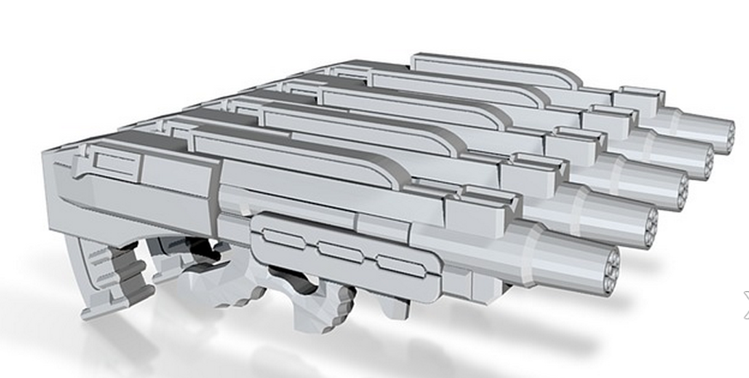
At some point I fell in love with the idea of a micro gatling gun.  A multibarreled rotary weapon that  would fire micro missiles.  The main inspiration for this design came from playing a very old shooter, command and conquer renegade.  It also has design motifs from the FN-P90 and the Thompson Sub-machine gun. 

This design started as inspired by the FN-F2000 and the FAMAS F1.  Both cutting edge weapon designs for modern militaries.  The design shifted from there.  Its become a far more elaborate weapon.  It's appearance is nice and light with a technical design.  My main reason for not using it as my base design is it was simply to difficult to modify the design into multiple weapon types.
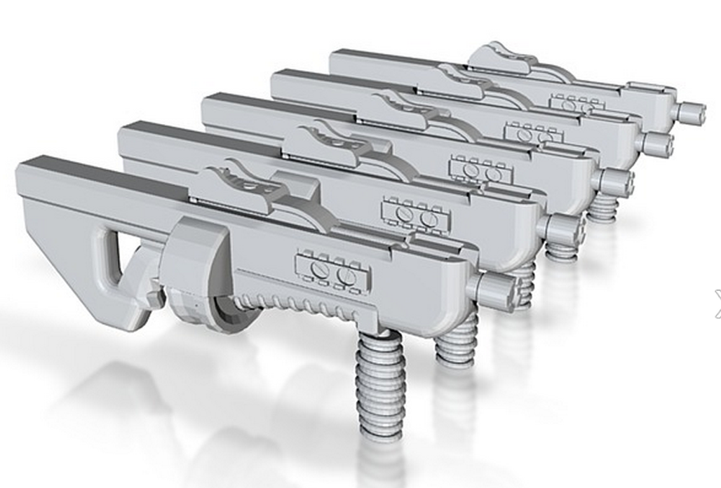

I have a love hate relationship with shotguns.  The short range, the heavy recoil, the small magazine, the inaccuracy.  When I do the math personally I always come up with a bad equation.  But I won't deny in other hands they can be fantastic.  Especially modern shotguns like the Pancor Automatic shotgun.  brutally effective at shredding cover and enemy flesh the pancor inspired me to make this design.  Unlike a lot of the other designs it doesn't have the underbarrel attachment mount. Instead it has traditional side rails for accessories.  The design is heavily rounded and smoothed like the entire weapon was made out of a single piece of carbon fibor.  In a scifi setting I picture shotguns as being the quickest, cheapest, and easiest weapons to make, even automatic ones.


When I started this project I had a good idea that I'd be making conventional weapons and energy weapons.  I first sought to make a separate energy weapon base for my weapons  I later decided to go a different route with the project.  This early design of a purely energy weapon design bares little resemblance to the mass production base I now use.  I picture it as a laser of some kind.  Chunky and durable its structure is more reminiscent of a prototype than a final field weapon.  But still it would look nice in the hands of soldier.

One of the early hallmarks of 40k and other hard science fiction settings has been the use of chemical and acids as weapons, a tactic our modern military hasn't adopted.  Of course the main reason for that is probably an effective delivery system.  This is my first take on a chemical weapon.  A two part compound sprayer that shoots narrow concentrations of chemicals at the enemy.  I'd imagine it as some form of magnetic acceleration unit that fires chemically infused needles.  Its a fun, 80's sort of scifi weapon.


Of course I can't neglect my newer designs.  One of the major holes in the line has been a rocket launcher. sure I could design a traditional tube style weapon but where's the fun in that.  No I opted for using the gyrojet base I designed for the Battle Cannon.  The barrel is inspired by the rocket launcher from Quake 3, one of my favorite shooters.  It uses a clip of oversize gyrojet rounds rather than a muzzle or breach load design like modern missile launchers. In field this would translate to a more stable, faster firing anti-tank weapon.  And of course it comes with shield and without as well as in a man portable version.

The other new design for the "Advanced" line is a lightning weapon.  here we see the lightning cannon design.  It has a central static transformer and 4 charge emitters around the outside.  Here is the heavy weapon version where we can see its intimidating blade like design.  Though short range and relatively inaccurate it can be devastating to electronic systems.  

The rifle variant of the lightning gun is more sleek with well defined blade like charge emitters  It forms a ball of electrons at its leading edge, building in charge until the transformer cycles.  The result is a devastating  if slow shock blast.

A group of 10 lightning pistols ready for deployment.  I imagine my lightning gun as a short range weapon so pistols makes perfect sense for the design.


Last post I previewed my new Starship Trooper style star marine design.  What I didn't preview were these. These torsos, inspired by Egyptian clothing and the powered armor design of my Star Marines, are intended as the basis for a lighter power armor design. Here we have the female design.  Its slimmer and slightly shorter than the male variant.  Yes it has breasts.  I've never quite understood the hate on female fantasy armor having breasts. Yeah I totally understand they are ridiculously impractical. And yes when treated poorly they are pretty much sexist short hand for "I like gurlz, yuck yuck".  But then I've never had a woman get upset because they have breasts.  Acknowledging sexuality isn't bad and hopefully I've done it without being offensive.

The male variant of the armor is virtually identical to the female.  Its got a clearly male shape.  It's a bit taller than the female variant but not by much.  This design's Egyptian motif is mostly in the mantle that graces its shoulders.  A mantle less design is in the works.  Its a bit more body armor like.

The shoulder pads for my new star marine designs.  Their leading edges are flat making them distinct from other shoulder designs.


The body of the new star marine armor is based off the smaller armor torso's I made above.  The Star Marine torso is completely enclosed. Normally the body would close entirely, here I've made 2 variants of the torso, one closed and the other, shown here, open.  The total figure is designed as an analogue for heavy armored space marine design.  Closed torso figures will stand approximately 44mm tall.  The gap in the open torso should fit any 28mm head once you cut off the neck.
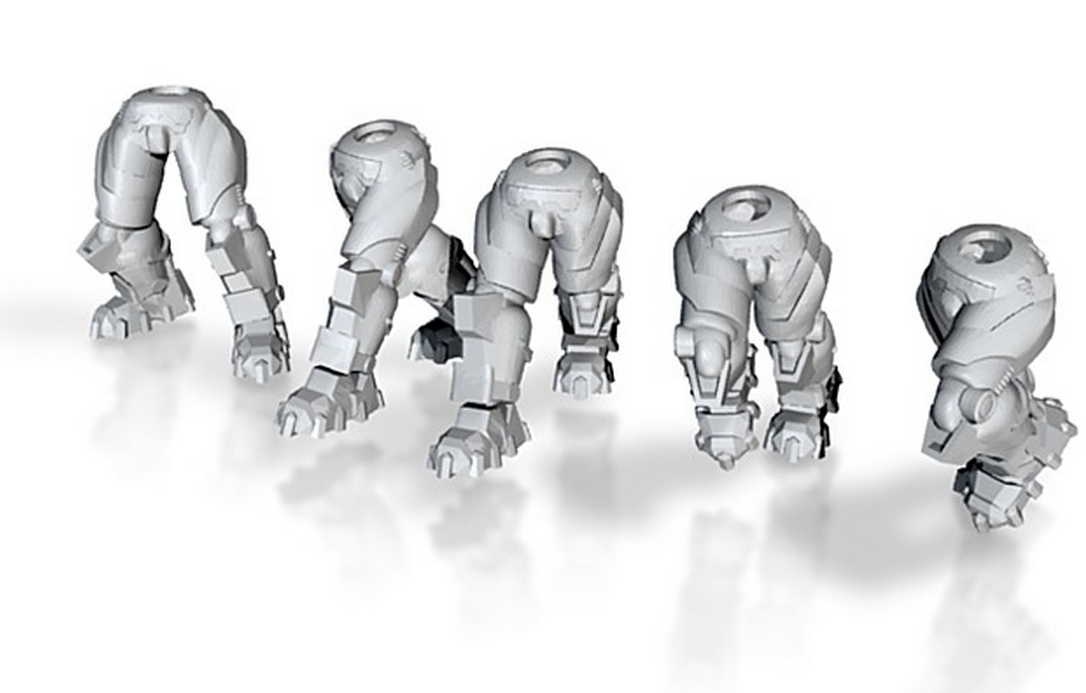
The legs to the most doing to make.  Sure I had the leg design finished when I flashed it last post.  But, the legs proved the most troublesome to upload.  Perhaps it was because of their intricate design, or maybe it was my own incompetence  but either way it took 6 or 7 tries to get them to upload.  Here we have advancing legs.

Well that's all for now, I'll try not to let the next update be a month away. :P Till then, enjoy.

Wednesday, January 2, 2013

How to Make Shoulder Pads


So I promised some time ago I’d show you how to make shoulder pads.  I’ve totally given up on the bell of lost souls contest so I’m just tossing this to my loyal followers on the blog.  I don’t have finished product pictures of my icons which just makes people a bit leery.  Couple that with the fact 3d design is a bit out of reach for the less tech savvy and you get a lot of people skimmed my tutorial but very few commented.  Doesn’t matter I don’t do this stuff to get money I do it because I enjoy it.

So shoulder pads

Now one quick disclaimer.  According to the depositions of the Chapterhouse Studios vs Games Workshop legal battle, Games Workshop claims copyright over the shape of shoulder pads. The judge has ruled in summary judgment that it is possible that GW can own the copyright.  Now this means two things, one that GW might own the shape of shoulder pads, IE a quarter ovoid with a raised rim, and two that CH must yet present evidence that implies otherwise.  Basically the shape of the shoulder pad is currently in contention.  As such if a person makes their own shoulder pads it may or may not be copyright infringement at this time.

Anyway let’s start with a sphere.  I’ve installed a free plugin called SCF Draw Tools.  It allows me to make shapes without the trouble of using the extrude or follow me functions that are normally needed to make a 2d shape a 3d object. Here I’ve started from a center point to make the sphere.


I’ve made the sphere approximately 8500 millimeters in diameter when scaled that will be 8.5mm. 
Of course a shoulder pad isn’t a sphere. Its an ovoid, its taller than it is wide. So we stretch it using the scale tool.  By grabbing the center handle and holding shift we can scale evenly along the axis.  Scaling up my 1.5 times should be about right.


Now obviously we need to break this down.  A shoulder pad is not a full ovoid, its one quarter of an ovoid. So we need to make this a quarter.  Now we are going to do this the hard way.  The Pro Version of Sketchup has these nice Boolean tools that let you intersect or union solid objects.  But I want to show you the freeway to do this. Let’s hope one day Trimble puts the boolean tools into the free version.  Till then we do things the hard way.

So join the ovoid into a group so it doesn’t interfere with the new geometry we are about to make.  And just to be safe lets hide it.  Now with the rectangle tool, starting at the center point of the axis, drag out a rectangle larger than the ovoid. Then use the extrude tool to make it a 3d rectangle. I like to do things in mirror so my shape rectangle only covers 1/8th the ovoid. This lets me modify one side of it and then mirror it down the center. It’s just lazier but it works.


Ok so now we have our two shapes but we need to intersect them.  We can do so by selecting the two objects and explode the two groups. Once they are no longer grouped select them then right click and choose “intersect faces with selection”  Now if we look at it transparent you’ll see the all the geometry is still present. But now where the two shapes overlap there are seems that we want to keep. We just need to delete the excess geometry we don’t want.


We go in with the eraser tool and remove the parts we don’t want.  This process isn’t necessary with the boolean tools in the Pro version but its not really worth the extra cost. There are some free plugins that offer versions of the boolean tools but I’ve never had good luck with them and since I have the Pro version I’ve never needed them.


Now we have the segment of the shoulder pad we need.  But we still need two things, the back needs hollowed to fit the arm, and the front needs a rim around the edge. So lets start with the hollow in the back.  Group the item again and then copy it.  Now use the “paste in place” function to put it back where it was.  Then switch to the scale function.  Using the corner handle scale it down so its slightly smaller.  You may have to play with it to size it correctly.  Once you have it how you want once more explode the shapes and intersect faces again.


Now we have the hollow shape so we can make the rim.  Start by copying the hollowed shape again. Then use the “paste in place” function.  Once you’ve done that use the scale tool just like before but scale it up so its larger than the original shape.


So now we need to take the center of the shape out to make it a rim.  We’ll use the same method we used before to do so.  Make a rectangular 3d object that is again larger than the original shape.  Now select the bottom and vertical edges use the “offset” tool on the side.  Then use the push pull tool to remove the main part and make an “L” shape.  Now we can combine the enlarged pad shape and the L to make the rim.  Once more using the explode and Intersect faces commands we can get the desired result.


At this point we have half a shoulder pad shape.  If we first select the geometry and tap the “control” key while using the move tool we can duplicate the design easily.  Then with the new geometry selected right click and choose “Flip Along” and select the appropriate axis.  Now just drag the geometry together so it is seemless.  At this juncture you can combine the two halves of the main body and the two halves of the rim together.  It’s important to keep the body of the pad and the rim of the pad separate for now.


Now we need to start on the icon for the shoulder pad.  To do so we need a plate that we will cut the icon out of.  We get this from copying the body of the shoulder pad, pasting it in place, and then enlarging it.  Here I’ve scaled the plate using the scale tool so its just slightly smaller than the rim I made. Don’t worry about the overhang at the back and bottom of the pad we’ll deal with that after we make our icon.


Now we need the icon itself.  Remember last time how I said keeping the different layers of the icon separate would be helpful.  This is where it will be helpful.  In this case we have 3 layers.  We are going to use each of these 3 layers as a cookie cutter to stamp out a layer for our icon.


To start put the 3 icons together like you’d want them to display.  Then using the move tool move them so they are centered around the same axis we are using to build our shoulder pad.  Once in place use the scale tool to stretch them so they are tall enough to pass through the shoulder pad.  Now we go back to the move tool.  When you select a single part with the move tool, you’ll see 4 “x” shaped points appear on each face. If we then select one it will allow us to rotate around the center of the object.  Rotate each layer of the icon so it goes through the face of the shoulder pad as shown below.


At this juncture we need to follow the same process we used before. First copy the plate.  Now select one of the icon layers and explode it and the plate. Now intersect with selection and remove the excess geometry. 


Once we have all the junk out of the way make the new shape a group and then paste the plate back in place so you can do the same thing to the other two icon parts.  Her we can see all 3 layers of the icon as their own rounded plate, while working I’ve hidden my shoulder pad body and rim so it’s not in the way.


We can now use the move tool to offset the layers giving them some relief to the design.  Select the layers you want to move, then select the move tool. Now hold the shift key to move the layers along an axis.  Here I’ve move it slightly along the green axis and blue axis to have this result.


Now we have a complete shoulder pad.  At this point if we have followed these steps our pad is complete. This multi-part file should print OK, but for the best results you should join all the faces and remove the internal geometry so its all one piece.  But if we want we can copy it to make multiples pads in a single file. We can rotate it to change orientation and so on.  Here I’ve duplicated the shoulder so it has 10 copies in a single file. Now I can scale it down by 1000% and use the STL export plugin to output it for shapeways.


Here are a couple pieces of advice to help new 3d modelers along. When I was first starting out the biggest problem I had was leaving geometry inside a model.  See when you make an STL and upload it for printing on Shapeways the process will combine each separate group into a “Shell” the shell has to be “watertight” in order for it to print.  That’s a fancy way of saying it has to be a solid 3d object.  Orphaned geometry hanging around either inside or outside a solid object will become its own shell because it’s not connected to anything.  But it’s a shell that can’t be printed because it’s not solid, it has a front but no back.  This means your print attempt will fail.  So it’s always a good idea to double check by going into each group and unhiding everything and removing the orphaned edges you might have missed.   The other problem I consistently had was what many at Shapeways call the “Wall thickness Lottery”.  Each material has specific rules regarding minimum thicknesses it can print in.  Unfortunately it’s very easy to have these thicknesses rejected if they are really close to the limitations.  Be mindful of your target material’s requirements and if necessary ask advise on the forums for guidance on how to resolve the issues you are having.  The shapeways community is quite friendly and willing to help.

Tuesday, December 18, 2012

3d Modeling and Printing Icons for 28mm Games

I had been writing this post for here but Bell of Lost Souls has a hobby article shopping spree contest going on so I'm posting it both places. If you want to support my plastic crack addition please vote over on the Bell of Lost Souls lounge for this hobby thread.  It will be broken into a couple seperate posts there with all the same images (linked from here) and dialog.

Well I was going to do this for my personal blog but figured I might as well do this on Bell of Lost Souls as well if there is a chance to win some free miniatures.  Ah the power of free.
I’m a big believer in free, or at the very least cheap, so I’m going to show you guys a pretty easy and relatively cost effective way to make some miniatures icons for your armies.

We are going to be using a single piece of software for this, Sketchup.  Sketchup has a free and a paid version, anything the paid version can do can also be done with the free version and a community created plugin. This makes sketchup very versatile even with out paying the 500 bucks for the “professional verson”.   In the past I’ve covered plugins on my blog to help people track down what they need to maximize their efficiency in sketchup.  You can find the blog post here, http://dynath.blogspot.com/2012/03/building-miniatures-in-sketchup.html.

We will also be using an 3d printing service called shapeways found here, http://www.shapeways.com. Shapeways is a community and sales site centered around customer created 3d printable objects. The price of shapeways products is set by the person that makes the object but ordering your own products for yourself will only cost you the actual production costs. While 3d printing can become quite expensive for large objects, small items like miniature bits are easy to make and cheap to order.

In this I’m going to show you how to make the master model for an icon plate.  This works very well for space marine armies but could also be used for any force icon.

First of course download and install Sketchup. I’ve also installed all of the plugins found in the blog post I’ve linked above.

Step 1: the background
Icons are easiest to mount if you put them on a background.  In this case I’m going to build a basic base that I can reuse.  I start by making a square.  Using the rectangle tool I drag out a square, when dragging the dashed line across the center tells you when you are making a square or a golden section. 


If you look at the bottom right corner in the info box you’ll see the size of the item I’m working with.  The square I started with is about 1000 millimeters.  This is too small.  Sketchup is designed to work with architecture so it can have some trouble when you make really small items.  So we need to work at a larger scale and then shrink the model down before we export it.  I like to work at 1000 times the final size. It’s is large enough I rarely have problems with geometry and the math for scaling is easy to figure out.


Here I’ve put some measuring lines on the square so we can see the size.  Then, with the square selected, I’ve selected the “Scale Tool”.  This puts little green handles around the sides of the object.  Then by dragging I can resize the square.  In this case I wanted to make a square that when output will be 15mm on each side.  So I drug the scale handle until the square has a size of about 15,000mm on each side.  Precision is not totally necessary but it helps. 


Well we have a nice two dimensional square but we need to have some depth to make a 3d model.  So we are going to choose yet another tool, the “Push/Pull tool”.   If we choose that tool, and then left click on a flat surface it can push or pull the surface out giving it thickness.  Watch the bottom left corner of the screen to determine how far you are pulling it.  I want the plate to be about 1mm thick so I’m making the larger model 1000mm tall approximately. 


Now we have a nice square background for our model.  We can select it and make it a group so it doen’t get lost.  Of course GW put some of their icons (on the drop pod sprues) on squares and circles and they are pretty boring so let’s fancy this up a bit.  Double click on our group to open it up.  Then select the “offset tool” this lets us click on a surface to offset a line inside that surface.  In this case I want to drop a line about 1000mm from the outside edge of our square. 


Now I’m going to use the “Push/pull tool” to push the surface in about 200mm.  this will make the total thickness in the middle of the plate about 0.8mm when done.  Shapeway has different materials with different minimum thicknesses so be aware of what your limits are for the material you want to print in.  I usually use Frosted Detail. It has lots of detail for miniatures and a 0.5mm minimum thickness so the thickness I just set it at is about perfect for a sturdy plastic plate.  Now lets add some rivits along the outside edge.  If you hover over the center of a line or shape a white dot will appear marking the center.  You can click on it with a tool to use it as an anchor.  You can do the same for existing points where a green dot will appear.  So using the “Line tool” find the center and corners of the outside edge and drag lines in so you have reference points.  Then switch to the “Circle tool”  find the center point of your lines and you can use it as the center of a circle.  Then using the “Eraser tool” you can remove the reference line.  Lastly go back to your “Push/Pull tool” to pull the circles out making 200mm tall rivets around the rim of your plate.


Step 2: The icon
So now we have our base plate, it’s scaled correctly, and it looks fancy.  So now we need an icon to put on the plate.  Sketchup has a bunch of basic drawing tools you can use to draw shapes.  Here I’ve drawn a new square and I’ve pulled out the drawing tools so you can see the pallet. 


Aside:  I will warn sketchup’s drawing tools are very limited so you might be inclined to use a separate program to design your icon.  Your best option for making geometry from an external file is to use a vector art software that can export DXF or DWF files. These are specific 2d vector formats Sketchup can process.  Doing an image in MS paint won’t be any help.  I own Adobe Illustrator which works for this but is very pricy. There are a number of free alternatives out there, check out Wikipedia or ask for recommendations from graphic artists if you can. An added advantage of separate programs like Illustrator is that they can often convert a raster image to a vector allowing you to use your own sketches or found images as the basis for your icon. 


We now need to make our icon. I’m a huge fan of the custom space marine chapter “the angry marines” so let’s make an angry marine icon.  Angry faces aren’t hard to make, they start with a circle.  So find the center of your square by drawing an X from corner to corner then draw out a large circle.  Using the X as a reference point draw in eyes. Then add horizontal reference bars to draw out a wide V on the forehead as a brow, and then a wide curve on the lower half as a frown.  I’ve added teeth hanging down below the frown to make it look meaner.  Below you’ll find images with my reference lines and after I’ve removed them. 


The angry marines icon isn’t really clever or detailed just a very angry, sort of goofy looking face.  Making your own custom icon might require a lot more detail.  When working on an icon remember to think in 3 dimensions.  All your lines have to have thickness and form a picture that can be made in relief.  So if you look at, say the lines separating the teeth I drew, you will notice they won’t come out in 3d.  You might have to work on that a bit to get things to come out how you want.  In this case I’ll go to the offset tool and shrink the teeth a bit to make them work as intended.
Now we can use the “Push/Pull tool” to give the icon depth.  I work from the deepest part down so I’ll pull the brow and frown out first. Then the eyes and teeth. And lastly the face itself.  The 3d model is now a relief all that’s left is to cap the bottom of the relief which is currently open and then remove any excess geometry.  Adding a line at the bottom of the relief will seal the model and you can erase excess lines around the outside of the model.

On a more complex icon you might want to make each of these parts a separate piece so you can move them around and scale them separately.  This can be necessary when working in specific circumstances such as when making icons on rounded surfaces.  In those instances you’d draw each level of the relief separately. Like show below, then pull each one out to give them depth.  Once layered on top of each other it’s no different than building them as one piece.


Step 3: put it all together
To complete our icon plate just put our relief icon on top of our base plate.  This gives us the 3d model we want of an icon plate suitable for slapping on a vehicle or building.


At this point we have a fantastic relief of the icon on a base plate but it’s 1000 times the size we need it at.  So again we use the “scale tool” this time selecting the entire completed icon and then the “scale tool”


Now we need to export it. Most 3d printing sites need a specific format of output file, usually Stereolithography files or STLs.  Shapeways is no exception.  For that we need to use an STL export plugin provided by the Sketchup community. You can find it linked from my earlier blog post.  Select your completed model and go to “Plugins”.  Now choose “Export STL file”. It will launch a dialog box to choose the size of your stl, select “millimeters” and it will then ask you where to save the file.


Step 4: Shapeways order
If you’ve done everything the file you exported will be print ready. You can start a shapeways account and upload the file there to order for yourself.   If you get an error when you try to purchase shapeways will give you feedback on what to fix. I’ve done some advise articles on this process on my blog and the shapeways community is fantastic for helping people sort out issues.
If you are interested later this week on my blog “dynath.blogspot.com” I will be demonstrating how this same process can be used to make other items such as shoulder pads.
Thank you and I shamelessly say “Vote for me”

Disclaimer: Warning reproduction of copyrighted designs constitutes intellectual property rights infringement. I neither condone nor suggest that you use these methods for such purposes.  I am not a representative of Trimble Inc. owners of Sketchup and all associated marks nor a representative of Shapeways.com owner of their associated marks.  Nor, and I can’t stress this enough, am I a representative of Games Workshop or representing their interests.